IMPORTING .STD (STAAD PRO© models)
versioni da Dicembre 2012 (> 10.01)
This topic is in English only.
Using Sargon or CSE you can import a model prepared in STAAD PRO, and the results got by using that program. However, as the documentation referring to Open Staad is quite lacking of several important info, several information cannot be transferred or it is not clearly explained how to do that. In the following a clear description of what is imported into Sargon/CSE will be given. All most important and needed information, however, is transferred.
Introduction
Importing a model into Sargon or CSE is a two steps procedure. First you create a text file by using STAAD. Then you import that text file using Sargon or CSE.
Let's have a model named "MODEL.STD" in a given folder. The first step is to create a text file named "MODEL.STD.TXT", in the same folder. This is done by executing a proper macro from within STAAD PRO. The macro itself is in the file "STD2STX.VBS", placed in the installation folder of Sargon (if you are using Sargon) or CSE (if you are using CSE). To execute a macro in STAAD PRO, open the model at hand, say "MODEL.STD", and run the analysis. Save results, so that they will be available for the macro. Then from the File Toolbar choose the "Run VB Macro" command, and select the file "STD2STX.VBS" located in Sargon or CSE installation folder. Then run the macro.
During the macro execution, if the results are not available you are prompted to decide if continue the execution or not. If you are not interested in post processing data, you can continue. If, on the other hand, you are interested in results (i.e. displacements, reactions, and member forces) then exit the macro ("Continue?" Answer: "No") and run the analysis.
Once the macro is executed successfully, a message will appear with the full path of the new file .STD.TXT just created. This file will be named "MODEL.STD.TXT" and is a text file with a wide subset of the information referring to you model.
Next step will be to open Sargon (or CSE) with a new blank file, and choose the command File-Import (in Sargon) or File-Import FEM Model (in CSE). Among the file types available you will find "STD.TXT (STAAD PRO)": choose that particular file format, browse your hard disk and select the file which you previously created in the model folder. This will run a command that will read the file and convert it into the Sargon (or CSE) file format.
If the user does decide to import the STAAD PRO results into Sargon or CSE, the conversion routine will:
1.Create a binary .DDB file containing the displacements of all nodes in all load cases;
2.Create a binary .SDB file containing the internal forces and stresses in all elements in all load cases;
3.Create a binary .RDB file containing the constraint reactions of all nodes in all load cases;
4.Mark the model as “solved” to make the data contained in the actual binary files accessible.
Some specific aspects of the main issues encountered when writing the conversion procedure are discussed in more detail below.
Units of measurement
File MODEL.STD.TXT is created or using [kN, meter] or using [kips, inch] units. This depends on the units used in STAAD PRO, if metric or imperial. Stresses are then given in kN/m2, and moments in kNm, or in ksi and kipin.
Z axis Up vs Y axis Up
Both Sargon and CSE use a "Z axis up" convention, so when reading a STAAD PRO file it's much better to have it created using the "Z axis up" convention as well. If Z axis up is used, then there is a perfect match between global axis (X, Y, Z) in STAAD and those in Sargon or CSE. If on the other hand the Yup flag is used in STAAD, then the conversion between global axes in STAAD and global axes in Sargon / CSE is as follows :
STAAD GLOBAL AXES |
SARGON CSE GLOBAL AXES |
X |
Y |
Y |
Z |
Z |
X |
Converting cross-section local axes
STAAD uses (x, y, z) local axes, while Sargon /CSE uses (1, 2, 3) local axes. However, generally these axes are placed differently over cross-sections, depending on the cross-section kind, and depending on the Z axis up, o Y axis up STAAD user's choice.
Generally speaking the following conversions apply for the most part of the cross sections (i.e. those doubly symmetric or with symmetry about weak axis):
STAAD MEMBER LOCAL AXES Y axis up |
SARGON CSE MEMBER LOCAL AXES |
x |
1, or x |
y |
3, or z |
z |
-2, or -y |
STAAD MEMBER LOCAL AXES Z axis up |
SARGON CSE MEMBER LOCAL AXES |
x |
1, or x |
y |
2, or y |
z |
3, or z |
Conversions adopted for the most part of the cross sections
However, some sections require a different mapping, according to the following table.
STAAD MEMBER LOCAL AXES |
SARGON CSE MEMBER LOCAL AXES |
Y axis up. C cross-sections (x, y, z) |
(1, -3, 2) |
Y axis up. L cross-sections (x, y, z) |
(-1, -2, 3) |
Y axis up. L-RA (reversed axes) cross-sections (x, y, z) |
(-1, -3, -2) |
Z axis up. C cross-sections (x, y, z) |
(1, -2, -3) |
Z axis up. L cross-sections (x, y, z) |
(-1, -3, -2) |
Z axis up. L-RA (reversed axes) cross-sections (x, y, z) |
(-1, 2, -3) |
Generally speaking a right tern (x, y, z) must be transformed into another right tern (1, 2, 3), and this can be done just in 8 different ways, preserving axis 1 direction. Each of the 8 possible ways to transform STAAD tern (x, y, z) to Sargon / CSE (1, 2, 3) is mapped to a "local tern mapping code", from 1 to 8.
STAAD MEMBER LOCAL AXES |
Sargon / CSE local axes |
LOCAL TERN MAPPING CODE |
(x, y, z) |
(1, 2, 3 ) |
1 |
(x, y, z) |
(1, -3, 2) |
2 |
(x, y, z) |
(1, -2, -3) |
3 |
(x, y, z) |
(1, 3, -2) |
4 |
(x, y, z) |
(-1, 3, 2) |
5 |
(x, y, z) |
(-1, -2, 3) |
6 |
(x, y, z) |
(-1, -3, -2) |
7 |
(x, y, z) |
(-1, 2, -3) |
8 |
The following table lists the conversion from Sargon / CSE to STAAD:
Sargon / CSE local axes |
STAAD MEMBER LOCAL AXES |
LOCAL TERN MAPPING CODE |
(1, 2, 3) |
(x, y, z ) |
1 |
(1, 2, 3) |
(x, z, -y) |
2 |
(1, 2, 3) |
(x, -y, -z) |
3 |
(1, 2, 3) |
(x, -z, y) |
4 |
(1, 2, 3) |
(-x, y, z) |
5 |
(1, 2, 3) |
(-x, -y, z) |
6 |
(1, 2, 3) |
(-x, -z, -y) |
7 |
(1, 2, 3) |
(-x, y, -z) |
8 |
Given this choice, we can say that the normal coding adopted by the conversion routine is the following:
STAAD MEMBER LOCAL AXES |
LOCAL TERN MAPPING CODE |
Y axis up. Generic cross-sections (x, y, z) |
4 |
Y axis up. C cross-sections (x, y, z) |
2 |
Y axis up. L cross-sections (x, y, z) |
6 |
Y axis up. L-RA cross-sections (x, y, z) |
7 |
Z axis up. Generic cross-sections (x, y, z) |
1 |
Z axis up. C cross-sections (x, y, z) |
3 |
Z axis up. L cross-sections (x, y, z) |
7 |
Z axis up. L-RA cross-sections (x, y, z) |
8 |
Generally speaking the conversion file "MODEL.STD.TXT" is written in such a way that the preceding rules are automatically applied by the conversion routine. This is got by assigning a "local tern mapping code" "0" to the cross-section in the file "MODEL.STD.TXT" (for an example of how this code is written in the file MODEL.STD.TXT, see next section).
If on the other hand this local tern mapping code in file "MODEL.STD.TXT" is overwritten by the user and set to a different value (from 1 to 8), then the program will use the coding related to the local tern mapping code specified by the user no matter the other possible rules.
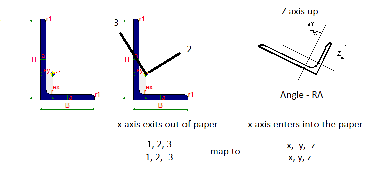
An example of conversion between Sargon / CSE and STAAD working environment
(in Sargon / CSE only axis 2 is displayed, being always axis 1 getting out of paper to the viewer, and axis 3 forming a right tern)
This may be needed if special cross sections are used, so that a correct remapping of the STAAD local tern (x, y, z) to the Sargon / CSE tern (1, 2, 3) must be specified. Imagine for instance that you have used a special, not symmetric cross section in STAAD which has axes (x, y, z) according to STAAD choices (also depending on the YuZup flag).
By editing the "MODEL.STD.TXT" file, at the row referring to that cross section, you will replace the code "0" with the code you need to set up a correct mapping (x, y, z)-> (1, 2, 3).
Obviously there are a number of consequences:
•changing STAAD axis "x" to -1 means reverting the direction of the arrow related to member axial axis. This need a change in load position definition, in load axial component when defined using local axes, and in the member forces as resulting on the analysis; of course member nodes (n1, n2) will be exchanged to (n2, n1).
•changing axis (y, z) to (3, 2) means changing end releases and member forces position. Also load components, if defined in local axes must be exchanged.
•generally speaking changing a sign of an axis means changing the sign of the member loads applied using local reference system, and changing member forces got by analysis;
This procedure, however, must not be done for standard cross-sections. The conversion for such cross sections is fully automatic
Converting Sectional forms
Before opening and reading the model which is to be imported, the conversion routine reads and imports the all the possible sectional forms in order to establish a suitable correspondence between the sectional forms in Sargon/CSE and those in STAADPRO.
The mapping file between the SARGON/CSE and STAAD PRO sectional forms is called "WSR_STD_SHPCVT.TXT" and can be found in the Sargon or CSE installation folder depending on the program you are using. This file will be used when a STAAD model is imported into Sargon or CSE. This file, known as the "mapping file", is usually the same for Sargon and CSE, and is structured as shown below.
$
$
IPE 100 IPE100
IPE 120 IPE120
IPE 140 IPE140
IPE R 140 IPE140R
IPE 160 IPE160
...
The first column indicates the names of the sections in the Sargon/CSE environment. The second column shows the corresponding section names in STAAD PRO. A section is identified by its name. If the name "beta" in STAAD corresponds to the name "alpha" in Sargon/CSE, then the sectional form "alpha" will be mapped to "beta" and assigned to members. To find out the properties of the sectional form "alpha", the program must open an archive of sectional forms of type .SMA (an .SMA file); in particular:
•if Sargon is in use, this will be the file "sargon.sma" in the Sargon program folder;
•if CSE is being used, the file is "cse.sma" in the CSE program folder.
If the first line of the mapping file contains a "$" or "\\" symbol that means it is a comment line.
The first 18 characters of the names are used for matching purposes. For two names to be matched, each of these 18 characters must be identical. STAAD names begins at column 41 in mapping file.
The conversion routine operates according to the following detailed rules:
1.The sectional forms in the .SMA file relevant to the program in use (Sargon or CSE) are read.
2.The entire conversion file is read into memory with its two columns of names.
3.To each cross section in the conversion file .STD.TXT is given a name and a type. The name is a string, the type is a number. Here is a typical block of information about cross sections in a .STD.STX file:
SECTION PROPERTY
9
1 "UC356X368X129" 3 610 0 3.68600E-01 3.55600E-01 1.64000E-02 3.69824E-03 8.60067E-03 1.52612E-06 1.46000E-04 4.02000E-04 1.75000E-02 1.04000E-02
2 "UC254X254X73" 3 610 0 2.54600E-01 2.54100E-01 9.31000E-03 2.18526E-03 4.82043E-03 5.76246E-07 3.91000E-05 1.14000E-04 1.42000E-02 8.60000E-03
3 "UB533X210X82" 3 610 0 2.08800E-01 5.28300E-01 1.05000E-02 5.07168E-03 3.67488E-03 5.15182E-07 2.01000E-05 4.75000E-04 1.32000E-02 9.60000E-03
4 "UB457X152X52" 3 610 0 1.52400E-01 4.49800E-01 6.66000E-03 3.41848E-03 2.21488E-03 2.13741E-07 6.45000E-06 2.14000E-04 1.09000E-02 7.60000E-03
5 "UA100X100X8" 3 641 0 1.00000E-01 1.00000E-01 1.55000E-03 5.33333E-04 5.33333E-04 3.34507E-08 6.11001E-07 2.35265E-06 8.00000E-03 8.00000E-03
6 "UC203X203X46" 3 610 0 2.03600E-01 2.03200E-01 5.87000E-03 1.46304E-03 2.98613E-03 2.21539E-07 1.55000E-05 4.57000E-05 1.10000E-02 7.20000E-03
7 "UB406X178X67" 3 610 0 1.78800E-01 4.09400E-01 8.55000E-03 3.60272E-03 3.40912E-03 4.61117E-07 1.36000E-05 2.43000E-04 1.43000E-02 8.80000E-03
8 "UB406X140X39" 3 610 0 1.41800E-01 3.98000E-01 4.97000E-03 2.54720E-03 1.62597E-03 1.07021E-07 4.10000E-06 1.25000E-04 8.60000E-03 6.40000E-03
9 "UA60x60x5" 3 641 0 6.00000E-02 6.00000E-02 5.82000E-04 2.00000E-04 2.00000E-04 4.89583E-09 8.07088E-08 3.17448E-07 5.00000E-03 5.00000E-03
The first field is the cross section number. Then there is the cross section name. Next the cross section country. The bold numbers in the 4th field are the cross section types (in STAAD PRO). The next field is local tern mapping code (see previous section) and is always written as "0" by VBA macro (meaning automatic remapping), albeit it can be edited and modified after the file MODEL.STD.TXT has been created by the macro, and before reading the file MODEL.STD.TXT into Sargon or CSE, in order to set a different mapping. After that field there is the "width", the "depth", Ax, Ay, Az, Ix, Iy, Iz, and finally Tw and Tf, the thicknesses. Before reading the file MODEL.STD.TXT, it is also possible to change names, type numbers and local tern mapping code according to the needs. This is normally NOT required, but may be helpful if needed to change from one cross section kind to another, or to improve conversion.
4.The sections in the STAAD PRO model are read from file "MODEL.STD.TXT" (as seen previously) and then transformed into Sargon/CSE-type sections following the procedure below.
a.If the name of the cross section is found in mapping file (second data column), and the cross section has types 631 or 632 (][ cross section), then the user is asked to set the clear distance between the two profiles using mm as length measurement unit; the cross section found in mapping file must be a channel.
b.If the name of the cross section is found in mapping file, and the cross section has types 633 ([ ] cross section), then the user is asked to set the clear distance between the two profiles using mm as length measurement unit; the cross section found in mapping file must be a channel.
c.If the name of the cross section is found in mapping file, and the cross section has type 642 (_||_ long side in contact cross section), then the user is asked to set the clear distance between the two profiles using mm as length measurement unit; the cross section found in mapping file must be an angle.
d.If the name of the cross section is found in mapping file, and the cross section has type 643 (_||_ short side in contact cross section), then the user is asked to set the clear distance between the two profiles using mm as length measurement unit; the cross section found in mapping file must be an angle.
e.If the name of the cross section is found in mapping file, and the cross section has type 616 (I I cross section), then the cross section will be added assuming a clear distance equal to 10mm between cross-sections; the cross-section found in mapping file must be an I rolled or H rolled cross section.
f.No matter if the name of the cross section has been found or not in mapping file , cross sections of types 667 672 and 677 (rectangular cross sections) are rebuild by using data written in .STD.TXT file.
g.No matter if the name of the cross section has been found or not in mapping file, cross sections of types 673 (Tee welded, i.e. sharp corners cross sections) are rebuild by using data written in .STD.TXT file.
h.No matter if the name of the cross section has been found or not in mapping file, cross sections of types 650 and 651 (box-like or rectangular-tube cross sections, sharp corners) are rebuild by using data written in .STD.TXT file. These have constant thickness.
i.No matter if the name of the cross section has been found or not in mapping file, cross sections of types 668 and 671 (round cross sections) are rebuild by using data written in .STD.TXT file.
j.No matter if the name of the cross section has been found or not in mapping file, cross sections of types 660 and 661 (circular hollow cross sections) are rebuild by using data written in .STD.TXT file.
k.If the name of the cross section is found in mapping file, the cross section is added as found in conversion file with no modification. So if the cross section is named AAA in STAAD and in conversion file this section is related to cross section BBB in Sargon / CSE archive, then cross section BBB will be applied.
l.If the name of the cross-section has NOT been found in mapping file, and no previous case is applicable then the program asks to the user to fill the necessary dimensions of the cross section (using mm as units), whose type has however been recognized as compatible with Sargon / CSE as it is written in file .STD.STX. The following table applies:
Type coded in .STD.TXT file |
Cross section kind |
610 |
I or H rolled cross section |
611 |
T cut from I or H rolled cross section |
616 |
I I composed by 2 rolled I or H |
620 |
T cut from I or H rolled cross section |
630 |
Rolled channel, parallel flange |
631 or 632 |
][ double channel |
633 |
[ ] double channel |
634 or 635 |
Cold formed channel (without or with lip) |
640 or 641 |
Rolled angle |
642 |
_||_ double angle long side |
643 |
_||_ double angle short side |
644 or 645 |
Cold formed angle without or with lip |
654 |
Rectangular hollow tube, round corners (RHS) |
655 |
Circular hollow sections |
662 or 663 |
Zee cold formed without or with lips |
664 |
Cold formed hat section |
674 |
Trapezoid: converted into a rectangular |
676 |
Generic cross section defined by area and area moments |
690 |
User Provided Table. I or H rolled cross section |
691 |
UPT. Parallel flange channel (rolled) |
692 |
UPT. Rolled angle |
693 |
|
694 |
UPT. Tee cut from I or H rolled. |
695 |
UPT. Circular hollow section. |
696 |
UPT. Rectangular hollow section. Sharp corners. |
697 |
UPT. Generic cross section defined by area and second area moment. |
698 |
UPT. I or H rolled cross section. |
700 or 701 |
UPT. _||_ double angle, long or short side in contact. |
702 |
UPT. ][ double channel. |
703 |
UPT. [ ] double channel |
771 |
plate property: unused |
m.If, finally, the name of the cross section has not been recognized in the mapping file, and the cross-section type is not one of those listed in the preceding table, then a dummy cross-section rectangular, and with the same name of the original cross section is applied.
The mapping file is easy to manage and the user can add any lines they require, maybe before importing the model.
As at November 2012, the conversion file contained about 4,000 sections. This include HEA, HEB, HEM, IPE, ILS, HLS, H, L, UPN, double L , double UPN and RHS sections, tubes, etc. etc.
It should be noted that the user can always ensure that a sectional form in STAAD PRO, say BBB, is converted correctly to a sectional form in Sargon/ CSE, simply by assuring that the desired form is in the .SMA archive with, say, name AAA, and that the Sargon/CSE-STAAD PRO mapping row between the names of the two sections is there in the mapping file (AAA BBB). Once carried out, the work will of course apply every time those sections, special or otherwise, are used in any model in the future.
When installing upgrades, in order to avoid overwriting your own mapping files and SMA archives, it is advisable to take a backup copy of both the mapping file and the SMA file.
Converting materials
Presently, only Isotropic materials are read and converted. No conversion is done for Orthotropic 2D or 3D materials.
During conversion, as material data extracted to .STD.TXT file by macro lacks info about yield and ultimate stresses, the user is asked to fill the missing data by choosing:
1.Or to assign fy and fu by browsing the Sargon / CSE material archive, to choose one material. That material will just be used to set fy and fu.
2.Or keep all data defined in the conversion file, and just add the yield stress value (fy) and the ultimate stress value (fu) by directly input those values.
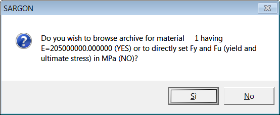
This question (see previous figure) is repeated for all materials defined in the model. The material is identified by its number and by its elastic modulus.
If the answer is Yes, then the following dialogue appears:

The user will browse through the archive and choose the material wished. The units of measurement used are those defined in the conversion file: [kN, meter] if metric units are used in the STAAD file, or [kips, inch] if imperial units are used int he STAAD file. However here no data must be input: you just have to choose a row and press Apply (Applica).
If the answer is "No" then the user must just fill the edit boxes referring to yield stress and ultimate stress, in the next dialog. This must be done using the units of measurement defined in the conversion file: [kN, meter] if metric units are used in the STAAD file, or [kips, inch] if imperial units are used int he STAAD file.
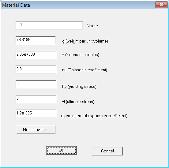
It is of course of the utmost importance that these data are filled correctly.
Converting supports
No skewed support is presently imported. Elastic supports are converted into translational or rotational springs in the Sargon / CSE environment.
Converting members
Members are mapped to beam elements in the Sargon CSE working environment. Offsets and end releases (0 or 1) are converted and assigned to elements according to those defined in the STAAD PRO working environment. No elastic release or partial release is presently imported. However, release elastic constants are written in the .STD.TXT file for future use.
As member end forces are directly read from results this will not affect stress state in using STAAD imported model in CSE.
If, on the other hand, the model has been imported into Sargon, these elastic releases will have to be re-assigned in view of a perfect match between the original and imported model.
Converting plates.
A constant thickness is assumed for plate elements. This constant thickness is got by a simple average of the 3 or 4 node-thicknesses of the element as defined in STAAD PRO. No orthotropic material assigned to plate elements is imported or assigned.
Converting solids
Due to the lack of documentation about solid elements in Open Staad reference manual, no material is assigned to solid elements, however their connectivity is read and assigned to solid elements in the Sargon / CSE working environment.
Converting members with the Truss, or NoTension, or NoCompression, or Cable flag
These elements are converted as beam members with properly auto assigned end releases. The following end releases are assigned automatically:
First Extreme: RxRyRz (R1R2R3) all rotations
Second Extreme: RyRz (R2R3) all rotations but torsional
In fact, in STAAD PRO elements with the flag Truss can still have shears inside. So they are mapped to beams properly released. The joist flag is not managed presently.
Converting primary load cases
Primary load cases are converted and added to Sargon / CSE model. The name of the primary load case is retained. The primary load case kind is converted according to the following rules.
Code STAAD Sargon / CSE
0 Dead Dead
1 Live Live
2 Roof live Live
3 Wind Wind
4 Seismic Seismic modal
5 Snow Snow
6 Fluids Live
7 Soil Live
8 Rain Live
9 Ponding Live
10 Dust Live
11 Traffic Live
12 Temp Temperature
13 Imperfection Live
14 Accidental Live
15 Flood Live
16 Ice Live
17 Wind ice Live
18 Crane hook Live
19 Mass Live
20 Gravity Gravity
21 Push Live
22 None Live
Converting load case combinations
What is named "load case combination" in the STAAD working environment, is simply named "combination" in the Sargon or CSE working environment.
In STAAD combinations do not have name, so they are named in Sargon / CSE according to their progressive number. Load factors are read from file .STD.TXT and assigned to combinations in Sargon / CSE model.
Results in combinations are got by Sargon / CSE at runtime, by linearly combining effects of load cases.
In Sargon / CSE combinations may be selected or not. Once imported in the new model, all combinations are selected by definition.
Converting single actions
The following single actions are converted and assigned in the new Sargon / CSE model:
1.Nodal forces and nodal moments.
2.Uniformly distributed forces over member elements (including d1 and d2 data, but not d3 which is assumed null).
3.Uniformly distributed moments over member elements (including d1 and d2 data, but not d3 which is assumed null).
4.Concentrated forces applied to member elements (including d1, but not d2 which is assumed null).
5.Concentrated moments applied to member elements (including d1, but not d2 which is assumed null).
6.Trapezoidal loads (forces per unit length) applied to member elements.
7.Linear varying loads (forces per unit length) applied to member elements
OpenSTAAD.Load functions "GetXXX" referenced in technical guide are unfortunately not enough to extract all data referring to loads applied.
So self weight is not converted due to a lack in Open Staad documentation.
Temperature loads are not converted nor assigned.
Element pressures are not converted and assigned.
The only loads which can be imported are those clearly referenced in the Open Staad documentation, for OpenSTAAD.Load object. While AddXXX functions are many, GetXXX functions are quite fewer.
Converting connection codes
Connection codes are not supported by STAAD, and it was not possible to use special rules to make Sargon/CSE able to assign needed connection codes (as done for SAP2000, for example, where conventional groups define connection codes on beam elements extremes). For this reason, user possibly needs to define connection codes in Sargon or CSE after the model has been imported from STAAD and before JNODES are searched for. If end releases are left unchanged and only connection codes are added, this operation does not imply a loss of results as no true modification is applied to analytical model. So imported results will be still available after connection codes definition. We recall here briefly that connection codes are useful when more elements meet in a node without any end release: connection codes will mark the elements which will be interrupted and connected, while element with no connection code will remain unmodified and will therefore be the "master" of the connection.
Converting the results (post-processing)
As already mentioned if results of the STAAD analysis are available, the import routine can create the binary files with the results in the Sargon/ CSE format. The following are imported:
1.All displacements of all nodes in all load cases and combinations (file MODEL.DDB).
2.All constraint reactions of all nodes in all load cases and combinations (file MODEL.RDB).
3.All internal forces at beams extremes in all load cases and combinations (file MODEL.SDB).
4.Currently, the stresses for two-dimensional and solid elements are not imported and are therefore null.